Zeven Development
 This is an image title
 This is an image title
 This is an image title
 This is an image title
 This is an image title
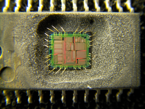
Hack the Chip
Use a General Purpose Microcontroller to replace your Custom Chip
Are you being squeezed by Supply Chain Shortages?
Is your chip no longer being made?
Is there a firmware bug
in your Chip?
Can't get the chip you need for your project?
Then Hack the Chip and make your own!
We built our product using Maxim's 1-Wire® to I2C DS28E17 bridge chip.
This allowed us to connect different I2C sensors, but discovered some issues.
- Only 3V3 Sensors could be used.
- If the Sensor required too much current it could cause a voltage drop or brown out, causing the DS28E17 to hang. Adding a large decoupling capacitor helped, but we were informed by Maxim to use the DS28E17 reset pin. Hello? I thought this was a 1-Wire® bus?
- No CRC Check on reading I2C data.
- Supply Chain Shortages. This chip is now really hard to get! Is the DS28E18 replacing the DS28E17?
- Supply and Demand led to steep price increases.
With these issues we then designed the next product using the DS28E18.
During the design phase we discovered a major issue.
- No Industry Standard I2C Clock Stretching! This was supported in the DS28E17 why did Maxim drop this critical compatibility feature? This issue was confirmed directly with Maxim.
So we can't get the DS28E17.
The new DS28E18 does not work.
What can we do?
Hack the Chip!
To do this we need to first define all the requirements and find a suitable General Purpose Microcontroller. As it turns out the AVR ATTiny85 will meet our requirements, but it is going to be a challenge to get the high speed working. No worries we have a few programming tricks up our sleeves.
| Feature | ATTiny85 | DS28E17 | DS28E18 |
|---|---|---|---|
| Available | Yes | No | Yes |
| Cost 01/2024 | $1.50 | $5.01 | $1.57 |
| Packaging | SOIC | TQFN | TDFN-CU |
| Pins | 8 | 16 | 8 |
| Power | 1.8-5.5V | 3V3 | 3V3 |
| MHz | 20 | N/A | N/A |
| Pins | 8 | 16 | 8 |
| Flash | 8K | N/A | N/A |
| SRAM | 512 Bytes | N/A | N/A |
| EEPROM | 512 Bytes | N/A | N/A |
| I2C | Yes | Yes | Yes |
| I2C Clock Stretching | Yes | Yes | No |
| UART | Software | No | No |
| 1-Wire® | Z-Wire | Yes | Yes |
| Standard Mode | Yes | Yes | Yes |
| Fast(Overdrive) Mode | High Speed | Yes | Yes |
| GPIO Pins | 3 | None | 2 |
| ADC Pins | 3 | None | None |
| SPI | 3-Wire | No | 4-Wire |
| Bit-Streaming | Yes | No | No |
| Upgradable Firmware | Yes | No | No |
| ROMID | 32 bit | 64 bit | 64 bit |
| Programmable ROMID | Yes | No | No |
Interrupts
The ATTiny85 runs on a 20MHz clock, but this is not fast enough to process a Z-Wire Read 1 that has a falling and rising edge in 1us. The trick here is check and clear the pending rising edge interrupt in the previous falling edge interrupt.
Bootloader
We created a custom bootloader for the ATTiny85 to allow for firmware updates, but there is no reserved bootloader space and we need to use interrupts in the bootloader for the serial communications, and in the main program. To make this work on the ATTiny85 we are going to have to use a shared Interrupt Vector Table and to run the bootloader code the user will have to install a jumper.
Note: You must erase and write the bootloader IVT fast enough so that in the event of a power loss you will not brick the unit. The Z-Wire board has enough capacitance on it to only last a couple of ms before the voltage drops below the operational minimum of 1.8V.
void writeFlashPage(uint16_t address)

{

    uint8_t i;

    uint16_t data;


    eeprom_busy_wait();


    boot_page_erase(address);

    boot_spm_busy_wait();


    for (i = 0; i < SPM_PAGESIZE; i
	+= 2) {

        data = *(uint16_t*)&USI_Buffer[i];

        boot_page_fill(address+i, data);

    }


    boot_page_write(address);

    boot_spm_busy_wait();

}
Coexist on the Same Wire
So how do you have two different protocols exist on the same wire?
The 1-Wire® protocol is a master/slave protocol. A low Reset pulse from the master is followed by Presence Detect from the slave alerts the master that the slave device is listening. If a slave is detected by the master it then sends out a command that can be followed by data from the master or slave.
To coexist on the same wire all you have to do is have the master send out a different length reset pulse and/or different command.
32-bit Address
Z-Wire uses a 32-bit Programmable Address instead of the 1-Wire® 64-bit ROM address. Every time the device is selected only 32-bits of address data needs to be sent resulting in shorter and faster communication times. Searching time is also significantly improved.
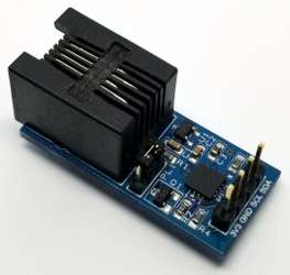
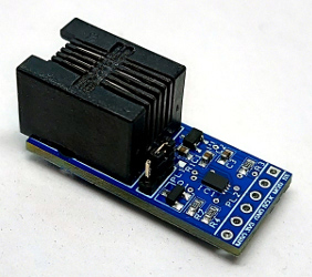
Z-Wire to I2C/IO
After carefully validating and testing all the requirements we now have created a replacement for the DS28E17 with new and improved features!
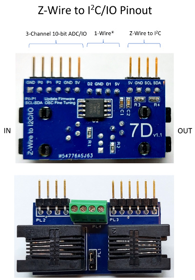
Feature List
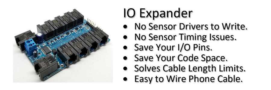
- Z-Wire bus can coexist on the same 1-Wire® bus.
- Connect multiple I2C buses to your Z-Wire bus on the IO Expander.
- I2C bus only at the end so it solves the limited cable length of I2C.
- Use multiple Z-Wire to I2C/IO adapters to connect multiple I2C sensors with the same I2C address.
- I2C bus is 5V instead of the DS28E17/DS28E18 3V3.
- 4.7kΩ I2C bus pull-ups on R3 and R4.
- PL1 jumper to select D1 or D2.
- Software selectable I2C bus speeds of 100kHz or 400kHz.
- Z-Wire Low or High(default) speed.
- Full Send and Receive CRC checking. DS28E17 does not support read I2C data CRC checking
- Compliant I2C Clock Stretching. DS28E18 does not support the industry standard I2C Clock Stretching at all.
- 32-bit programmable addresses instead of Maxim 1-Wire® devices using fixed 64-bit ROM addresses. Results in faster searching and device selection.
- 3 Digital IO/10-bit ADC pins.
- 20mA current sourcing on P0 and P1. 2mA only on P3.
- Z-Wire requires 3-wires to work; 5V, GND, and a single bidirectional data pin. Parasitic control is not supported.
- Advanced brownout detection. Fixes DS28E17 lockup issues that required additional reset pin control.
- Hardware watchdog monitoring for maximum reliability.
- Downloadable firmware. Keep up to date with the latest updates.
- Low standby power 5mA typical with P0-P2 as inputs and low speed; 18mA with P0-P2 as outputs or high speed.
- 39.4mm x 22.2mm.
1-Wire is a registered trademark of Maxim Integrated Products, Inc.