Zeven Development
 This is an image title
 This is an image title
 This is an image title
 This is an image title
 This is an image title
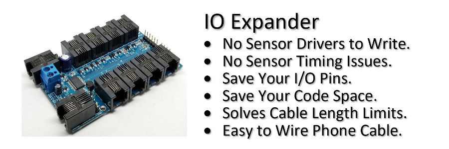
Connect OLED Screens and I2C Sensors
Over 100ft
Away!
Use the IO Expander and accessories to connect OLED Screens and I2C Sensors over a 100ft away.
Need to add OLED screens at the sensors location for meaningful reporting that are too far away from your project?
Too many sensors to connect on the I2C bus? Then you need the IO Expander! With the 1-Wire® to I2C adapter, add as many I2C buses as needed on your 1-Wire® bus.
Need multiple 1-Wire® buses? The IO Expander will support up to 16 at the same time.
Need even more? Then link up to 255 IO Expanders together; the IO Expander truly delivers extreme connectivity!
Feature List
- Use Cheap 128x64 OLED Screens.
- Use Multiple OLED Screens on a Single 1-Wire® Bus.
- Use Different OLED Screen Sizes.
- Add as many I2C Buses as Needed.
- Never run out of I2C Address. Just add another I2C Bus.
- Easy to use Graphics Commands.
- 1-Wire® Standard and Overdrive for fast screen updates.
- No 1-Wire® Driver Required. Save Code Space.
- No OLED Drivers Required. Save Code Space.
- No OLED Fonts Required. Save Code Space.
- No DS18B20 Temperature Driver Required. Save Code Space.
- No I2C Sensor Drivers Required. Save Code Space.
- No Extra Power Supply Needed.
- Easy to connect RJ11 phone wire.
- Easy to add Sensors on 1-Wire® Bus.
- Hot Pluggable 1-Wire® Bus.
Parts used to build the OLED demo.
- IO Expander
- 1-Wire® to I2C.
- 1-Wire® Junction
- Splitter
- Arduino Nano.
- RJ11 Keystone Screw Terminal Jack.
- 50ft 4C4P RJ11 Wire.
- 7ft 4C4P RJ11 Wire.
- DHT22 Temperature/Humidity Sensor.
- I2C Si7021 Temperature/Humidity Sensor.
- SSD1306 128x32 OLED 0.91".
- SSD1306 128x64 OLED 0.96".
- SSD1106 128x64 OLED 1.3". Note: Screens are fragile! Make sure you order them in cases.
- SSD1309 128x64 OLED 2.42".
- 2.54mm Header Wire.
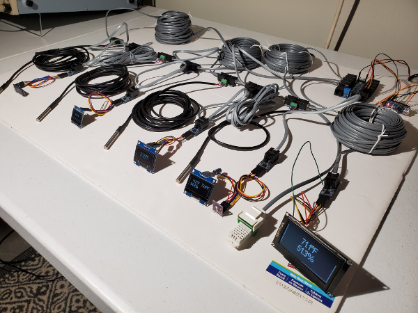
Wiring Diagram
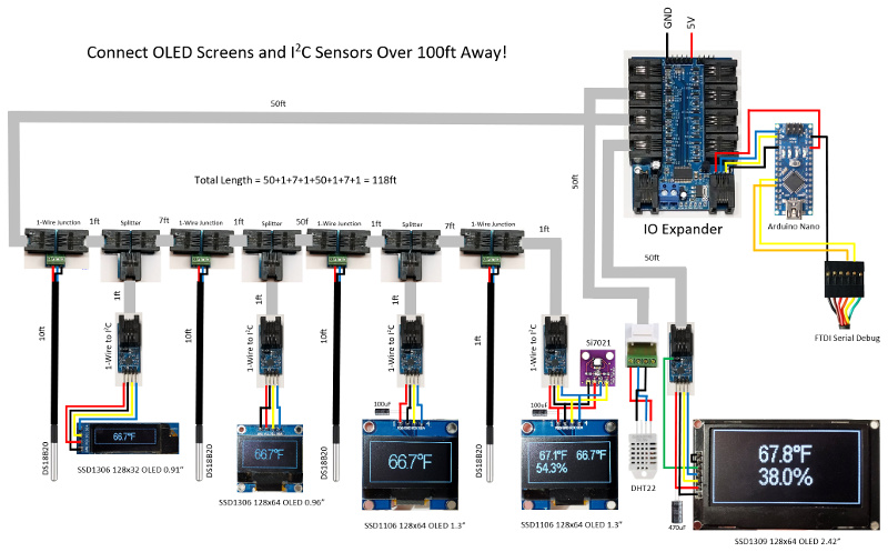
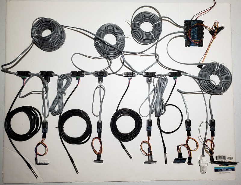
Overhead View
Arduino code to run this demo.
/* IO Expander OLED sketch

 *

 *  Make sure you increase the SERIAL_RX_BUFFER_SIZE in Arduino/hardware/arduino/avr/cores/arduino/HardwareSerial.h

 *  from 64 to 256.

 */


#define SERIAL_RX_BUFFER_SIZE   256


#include <SoftwareSerial.h>

#include <avr/wdt.h>

#include "IOExpander.h"


#define FAHRENHEIT


#define OLED_SCREENS            5

#define TEMP_SENSORS            4

#define HUMIDITY_SENSORS        2


#define ONEWIRE_TO_I2C_ROM1     "i4s51"

#define ONEWIRE_TO_I2C_ROM2     "i4s2e"

#define ONEWIRE_TO_I2C_ROM3     "i4s24"

#define ONEWIRE_TO_I2C_ROM4     "i4sc0"

#define ONEWIRE_TO_I2C_ROM5     "i2see"


#define ONEWIRE_TEMP_CONVERSION "t4s0;tt"

#define TEMP_SENSOR1            "t4r4c"

#define TEMP_SENSOR2            "t4r57"

#define TEMP_SENSOR3            "t4r76"

#define TEMP_SENSOR4            "t4r300"

#define HUMIDITY_SENSOR1        "st8"

#define HUMIDITY_SENSOR2        "s6t5"


#define INIT_OLED_SSD1306_32    "st10;si128,32"

#define INIT_OLED_SSD1306_64    "st10;si128,64"

#define INIT_OLED_SSD1106       "st13;si128,64"

#define INIT_OLED_SSD1309       "g1o0,10;s2t10;si128,64"


#define SERIAL_DEBUG


#ifdef SERIAL_DEBUG

SoftwareSerial swSerial(8,7);

#endif


struct TS {

  bool update;

  float temp;

  bool error;

};


struct HS {

  bool update;

  float temp;

  float humidity;

  bool error;

};


int led = 13;


#ifdef FAHRENHEIT

#define C2F(temp)   CelsiusToFahrenheit(temp)

float CelsiusToFahrenheit(float celsius)

{

  return ((celsius*9)/5)32;

}

#else

#define C2F(temp)   (temp)

#endif


bool init_oled[OLED_SCREENS] = {true, true, true, true, true};

TS ts[TEMP_SENSORS];

HS hs[HUMIDITY_SENSORS];


void ReadTempSensor(TS* ts, char* ts_read)

{

  float temp = ts->temp;


  SerialCmd(ts_read);

  ts->error = !SerialReadFloat(&ts->temp);

  SerialReadUntilDone();

  if (ts->error) ts->temp = 0;

  else ts->temp = roundf(ts->temp * 10) / 10;

  ts->update = (temp != ts->temp);

}


void ReadHumiditySensor(HS* hs)

{

  float temp = hs->temp;

  float humidity = hs->humidity;


  SerialCmd("sr");

  hs->error = !(SerialReadFloat(&hs->temp) && SerialReadFloat(&hs->humidity));

  SerialReadUntilDone();

  if (hs->error) hs->temp = 0;

  else {

    hs->temp = roundf(hs->temp * 10) / 10;

    hs->humidity = roundf(hs->humidity * 10) / 10;

  }

  hs->update = (temp != hs->temp || humidity != hs->humidity);

}


void SerialPrintDecimal(const char* str, float decimal, char error)

{

  Serial.print(str);

  if (error) Serial.print(F("NA"));

  else Serial.print(decimal, 1);

  Serial.print("\"");

}


void SerialPrintUnits(void)

{

  Serial.print(",248,\""

  #ifdef FAHRENHEIT

            "F"

  #else

            "C"

  #endif

    "\"");

}


void SerialDrawBorder(uint8_t height)

{

  if (height == 32) Serial.print(";sh0,0,128;sh0,31,128;sv0,1,30;sv127,1,30");

  else Serial.print(";sh0,0,128;sh0,63,128;sv0,1,62;sv127,1,62");

}


void setup() {

  Serial.begin(115200);

  Serial.setTimeout(5000);                // 5 sec delay between DHT22 reads

#ifdef SERIAL_DEBUG

  swSerial.begin(115200);

  swSerialEcho = &swSerial;

#endif

  pinMode(led, OUTPUT);

  wdt_enable(WDTO_8S);

}


void loop() {

  uint8_t i;

  static uint32_t last_millis = 0;

  static TS ts[TEMP_SENSORS];

  static HS hs[HUMIDITY_SENSORS];


  while (Serial.available()) Serial.read(); // Flush RX buffer

  Serial.println();

  if (SerialReadUntilDone()) {

    // First do a 1-Wire temperature measurement on all DS18B20 sensors

    SerialCmdDone(ONEWIRE_TEMP_CONVERSION);


    // Read the Si7020 humidity sensor

    if (SerialCmdNoError(ONEWIRE_TO_I2C_ROM4)) {

      if (SerialCmdDone(HUMIDITY_SENSOR1)) {

        ReadHumiditySensor(&hs[0]);

      }

    }

    else init_oled[3] = true;


    // Read DHT22 humidity sensor every 2 seconds

    if (millis() - last_millis >= 2000) {

      SerialCmdDone(HUMIDITY_SENSOR2);

      ReadHumiditySensor(&hs[1]);

      last_millis = millis();

    }


    // Read 1-Wire temperature sensors

    ReadTempSensor(&ts[0], TEMP_SENSOR1);

    ReadTempSensor(&ts[1], TEMP_SENSOR2);

    ReadTempSensor(&ts[2], TEMP_SENSOR3);

    ReadTempSensor(&ts[3], TEMP_SENSOR4);


    if (SerialCmdNoError(ONEWIRE_TO_I2C_ROM1)) {

      if (init_oled[0]) {

        if (SerialCmdNoError(INIT_OLED_SSD1306_32)) {

          init_oled[0] = false;

          ts[0].update = true;

        }

      }

      if (!init_oled[0] && ts[0].update) {

        SerialPrintDecimal("st10;sc;sf1;sa2;sd63,8,\"", C2F(ts[0].temp), ts[0].error);

        if (!ts[0].error) SerialPrintUnits();

        SerialDrawBorder(32);

        SerialCmdDone(";sd");

        ts[0].update = false;

      }

    }

    else init_oled[0] = true;


    if (SerialCmdNoError(ONEWIRE_TO_I2C_ROM2)) {

      if (init_oled[1]) {

        if (SerialCmdNoError(INIT_OLED_SSD1306_64)) {

          init_oled[1] = false;

          ts[1].update = true;

        }

      }

      if (!init_oled[1] && ts[1].update) {

        SerialPrintDecimal("st10;sc;sf2;sa2;sd63,19,\"", C2F(ts[1].temp), ts[1].error);

        if (!ts[1].error) SerialPrintUnits();

        SerialDrawBorder(64);

        SerialCmdDone(";sd");

        ts[1].update = false;

      }

    }

    else init_oled[1] = true;


    if (SerialCmdNoError(ONEWIRE_TO_I2C_ROM3)) {

      if (init_oled[2]) {

        if (SerialCmdNoError(INIT_OLED_SSD1106)) {

          init_oled[2] = false;

          ts[2].update = true;

        }

      }

      if (!init_oled[2] && ts[2].update) {

        SerialPrintDecimal("st13;sc;sf2;sa2;sd63,19,\"", C2F(ts[2].temp), ts[2].error);

        if (!ts[2].error) SerialPrintUnits();

        SerialDrawBorder(64);

        SerialCmdDone(";sd");

        ts[2].update = false;

      }

    }

    else init_oled[2] = true;


    if (SerialCmdNoError(ONEWIRE_TO_I2C_ROM4)) {

      if (init_oled[3]) {

        if (SerialCmdNoError(INIT_OLED_SSD1106)) {

          init_oled[3] = false;

          ts[3].update = true;

        }

      }

      if (!init_oled[3] && (ts[3].update || hs[0].update)) {

        SerialPrintDecimal("st13;sc;sf1;sa1;sd60,12,\"", C2F(hs[0].temp), hs[0].error);

        if (!hs[0].error) SerialPrintUnits();

        SerialPrintDecimal(";sd60,32,\"", hs[0].humidity, hs[0].error);

        if (!hs[0].error) Serial.print(",\"%\"");

        SerialPrintDecimal(";sd121,12,\"", C2F(ts[3].temp), ts[3].error);

        if (!ts[3].error) SerialPrintUnits();

        SerialDrawBorder(64);

        SerialCmdDone(";sd");

        ts[3].update = false;

        hs[0].update = false;

      }

    }

    else init_oled[3] = true;


    if (SerialCmdNoError(ONEWIRE_TO_I2C_ROM5)) {

      if (init_oled[4]) {

        if (SerialCmdNoError(INIT_OLED_SSD1309)) {

          init_oled[4] = false;

          hs[1].update = true;

        }

      }

      if (!init_oled[4] && hs[1].update) {

        SerialPrintDecimal("st10;sc;sf1;sa2;sd63,12,\"", C2F(hs[1].temp), hs[1].error);

        if (!hs[1].error) SerialPrintUnits();

        SerialPrintDecimal(";sd63,32,\"", hs[1].humidity, hs[1].error);

        if (!hs[1].error) Serial.print(",\"%\"");

        SerialDrawBorder(64);

        SerialCmdDone(";sd");

        hs[1].update = false;

      }

    }

    else init_oled[4] = true;


#ifdef SERIAL_DEBUG

#endif

  }

  else {

    digitalWrite(led, HIGH);                // blink Arduino led for IO Expander failure

    delay(500);

    digitalWrite(led, LOW);

    delay(500);


    for (i = 0; i < OLED_SCREENS; i++) init_oled[i] = true;

  }

  wdt_reset();

}
SSD1309 128x64 OLED 2.42".
The documentation for the larger 2.42" OLED is not good, so I've added some additional information on how to properly use it with the 1-Wire® to I2C adapter.
The display comes shipped by default as SPI so the first thing you have to do is convert it to I2C. This means you need to get the solder iron out and remove and add some SMD 0603 resistors.
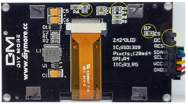
- Remove R4 and put it on R3.
- Add 0 ohm resistor at R5 and R7.
- Add jumper to CS-DS. This will effectively GND DC for I2C address selection of 0x3C. If you would like to use the alternate I2C address of 0x3D then remove the jumper and connect DC to VCC (3V3) instead.
- Connect a wire from RES pin to the unjumpered pin of PL1 (D2) on the 1-Wire® to I2C adapter. This will be used as a GPIO line to send a required reset pulse after power up of the OLED display.
This display controller requires a reset pulse on the RES pin to be sent after VCC is stable. According to the SSD1309 display controller you must set RES LOW for at least 3us and then HIGH. It's also useful to have access to a reset line on this display in the event of a panel lockup, where you can reset and reinitialize it without having to power down your whole system.
To send a reset pulse using the IO
Expander use the gpio command
on the selected pin and specify a duration.
Here we use the [g]pio
command on pin [1] as an [o]utput of [0] or low for [10]ms. After
the duration the pin will remain high.
>g1o0,10
ok
>
The larger 2.42 OLED display uses a simple internal switch-cap charge pump that converts the incoming 3V3 to a high 15V voltage drive for the OLEDs. The display draws on average about 50mA from the 3.3V supply but the required inrush, especially over longer cable lengths requires that you add an additional 470uF electrolytic capacitor across VCC and GND on the incoming 3V3. Make sure you connect the minus side to GND! If you are using header connectors, just insert the capacitor into the pins.
For the smaller SSD1106 1.3" it also uses an internal charge pump that converts the incoming 3V3 to 7V to drive the OLEDs, so for longer cable lengths you will also need to add an additional 100uF electrolytic capacitor at the incoming 3V3.
This demo uses Splitters as 1-Wire® stubs to connect the 1-Wire® to I2C adapters to the OLED displays and I2C Si7021 sensor.
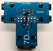
Splitter used as two 1-Wire® drops on D1 and D2, with R1 and R2 as 100Ω
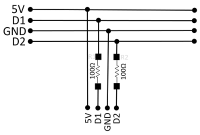
In order to connect as many 1-Wire® sensors on to a single wire the OLED screen and sensors are connected to the 1-Wire® bus as stubs, but there is an impedance mismatch at the branch point. Reflections from the end of the stub return to the main trunk, delayed only by the time it takes for the signal to travel the length of the stub. These reflections can then cause problems for the other slaves on the network. A resistor in series with the stub will reduce the severity of the mismatch and the amplitude of the reflected energy. The resistor mitigates adverse effects from stub-generated reflections on the main trunk
Guidelines for Reliable Long Line 1-Wire® Networks
1-Wire® Protocol
In order to efficiently run OLED displays, the IO Expander supports actively driven 1-Wire® Overdrive speeds of up to 75.47kHz at over 100ft! If you need to go several hundred feet then you can still fall back to the slower standard speed of 15.38kHz. Native Temperature sensors like the DS18B20 do not support the Overdrive speed so can you mix devices with different speeds and the IO Expander will automatically change speeds to match the device on the same 1-Wire® bus. The Overdrive speed is slower than the 400kHz on the I2C bus that is connected to the OLED screens, but it is fast enough for sensor status reporting right at the sensor location.
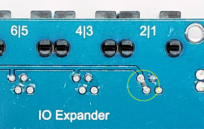
In order to use Overdrive speeds you must use a strong pullup of 2.2k as close to the CPU IO pin as possible. For this demo we used pin 4 which already came with a 2.2k pullup, but for pin 2 we need to add one. The simplest way is to solder a 2.2k 0603 resistor between the pins on the RJ11 plug on the port on the underside of the IO Expander PCB.
The IO Expander supports three different commands to control 1-Wire® devices.
| cmd | Function |
|---|---|
| o | [o]newire direct control. |
| i | 1-Wire® [i]2c control. |
| t | 1-Wire® [t]emperature sensors. |
On the [o]newire bus on pin [4], [f]ind all the ROMs.
>o4f

				28ffe835c3160376

				28ffea20c316034c

				28ff19f4c2160300

				28fffd34c3160357

				197a28030000002e

				19ad200300000051

				19ed200300000024

				198f1103000000c0
>
[i]2c devices on pin [4], [f]ind all the ROMs.
>i4f

				197a28030000002e

				19ad200300000051

				19ed200300000024

				198f1103000000c0
>
[t]emperature devices on pin [4], [f]ind all the ROMs.
>t4f

				28ffe835c3160376

				28ffea20c316034c

				28ff19f4c2160300

				28fffd34c3160357
>
So how hard is it to use the IO Expander? Judge for yourself by example.
[t]emperature sensor on pin [4] [s]elect ROM [76]. Perform a [t]ermperature conver[t], and finally do a [t]emperature [r]ead.
>t4s76;tt;tr

				28ffe835c3160376

				ok

				17.9375
>
It's that easy!
Hot Pluggable!
One of the unique features of the IO Expander is that it has been designed to support hot pluggable devices. This means that if you have a sensor or OLED display go bad on you, you don't have to power down your system to replace it. While it is still powered remove the RJ11 plug and reconnect a new sensor or OLED screen. Also for this to happen you have to make sure that your code has been written to detect and reinitialize. Some sensors don't have the necessary protection, so do this at your own risk. Any 1-Wire® connection should be ok, as the 1-Wire® driver on the IO Expander has been specially written to support this unique feature.
So get your IO Expander today and build your system!
1-Wire is a registered trademark of Maxim Integrated Products, Inc.